:max_bytes(150000):strip_icc()/muffler-undercarriage-56a056aa3df78cafdaa11600.jpg)
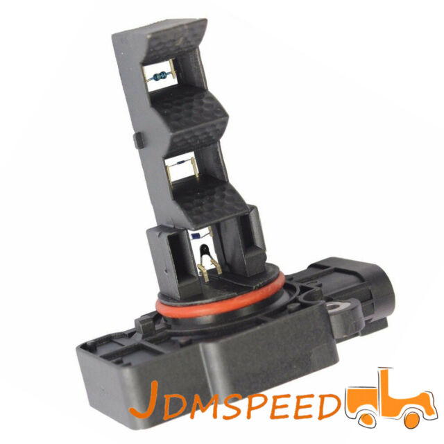
The integrated electronic circuit converts the measurement into a calibrated signal which is sent to the ECU. The current or voltage drop is proportional to the mass of air flowing past the wire. As more current flows, the wire’s temperature increases until the resistance reaches equilibrium again. When air flows past the wire, the wire cools, decreasing its resistance, which in turn allows more current to flow through the circuit or causing a smaller voltage drop over the wire. The wire’s electrical resistance increases as the wire’s temperature increases, which varies the electrical current flowing through, or the voltage over the circuit, according to Ohm’s law.

This is achieved by heating a wire suspended in the engine’s air stream, like a toaster wire, with either a constant voltageover the wire or a constant current through the wire. The theory of operation of the hot wire mass airflow sensor is similar to that of the hot wire anemometer (which determines air velocity).

Many VAF sensors have an air-fuel adjustment screw, which opens or closes a small air passage on the side of the VAF sensor. A voltage is applied to the potentiometer and a proportional voltage appears on the output terminal of the potentiometer in proportion to the distance the vane moves, or the movement of the vane may directly regulate the amount of fuel injected, as in the K-Jetronic system. The vane moves in proportion to the airflow. The VAF (volume air flow) sensor measures the air flow into the engine with a spring-loaded air flap/door attached to a variable resistor ( potentiometer).


 0 kommentar(er)
